Jumia

Thursday, June 14, 2018

THE WORLD CUP

Click Like and Share if you like what you see

Russia 2018 World Cup Preview: Russia vs Saudi Arabia Read more: https://www.naija.ng/1175133-russia-2018-world-cup-preview-russia-saudi-arabia.html?source=notification#1175133


Russia 2018 World Cup Preview: Russia vs Saudi Arabia Author: Akan Anwankwo UPDATED: 4 HOURS AGO VIEWS: 13671 Category: Sports, Football News, World News, Russia 2018 FIFA WORLD CUP - Russia will begin their World Cup campaign against Saudi Arabia - Both teams have had poor run of matches coming into the tournament - The teams will be meeting for the second time in their history The long wait for the Russia 2018 FIFA World Cup will begin today, June, 14, as the host nation, Russia, will be slugging it out with Saudi Arabia in the opening fixture. Both teams will be vying for honours in Group A alongside North African side Egypt and South America power house Uruguay. Russia have had a poor run of form losing seven games in a row and their last win was against South Korea last October. READ ALSO: Chelsea move a step closer in landing Sarri at Stamford Bridge Saudi Arabia on the other hand, have also lost three straight friendlies to Italy, Peru and Germany as both sides will be looking to end their winless streak. PAY ATTENTION: Click on link to get World Cup fixtures on NAIJ.com History favours the Eastern European going into this match as no host nation have lost their opening fixture in the biggest football showpiece. PAY ATTENTION: Click on link to get World Cup results and standings on NAIJ.com However, both teams have played just once as the Middle East nation recorded a commanding 4-2 victory in a friendly match. Possible line-ups Russia: Igor Akinfeev; Mario Fernandes, Fedor Kudryashov, Sergey Ignashevich, Yuri Zhirkov; Roman Zobnin, Daler Kuzyaev, Alan Dzagoev, Aleksandr Samedov, Aleksandr Golovin; Fedor Smolov Saudi Arabia: Abdullah Al-Mayouf; Usamah Husawi, Omar Hosawi, Yasser Al-Shahrani, Mohammed Al-Barik; Abdullah Otif, Salman Al-Faraj, Yahya Al-Shihri, Taisir Al-Jassim, Salem Al Dosari; Fahad Al-Molad Time: 4pm (Nigerian time) Date: Thursday, June, 14 Venue: Luzhniki Stadium, Moscow Which Nigerian player do you expect to shine at the Russia 2018 World Cup? (Street Gist) - on NAIJ.com TV SUBSCRIBE TO WATCH NEW VIDEOS Source: Naija.ng Read more: https://www.naija.ng/1175133-russia-2018-world-cup-preview-russia-saudi-arabia.html?source=notification#1175133

Playlist

Click Like and Share if you like what you see


Build your own inverter Today

  • Operating Principle of an Inverter

    An inverter can be taken as a crude form of UPS. Obviously the main use of an inverter is only for powering common electrical appliances like lights and fans during a power failure.
    As the name suggests the basic function of an inverter is to invert an input direct voltage (12VDC) into a much larger magnitude of alternating voltage (generally 110VAC or 220VAC).
    Before learning how to build an inverter, let’s first understand the following fundamental elements of an inverter and its operating principle:
    Oscillator: An oscillator converts the input DC (Direct Current) from a lead acid battery into an oscillating current or a square wave which is fed to the secondary winding of a power transformer. In the present circuit, IC 4049 has been used for the oscillator section.

    Transformer: Here the applied oscillating voltage is stepped up as per the ratio of the windings of the transformer and an AC much higher than the input DC source becomes available at the primary winding or the output of the inverter.
    Charger: During power backups when the battery gets discharged to a considerable level, the charger section is used to charge the battery once the AC mains is restored.

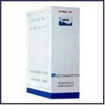
    EP3000 series sine wave inverters. 1000W - 6000W available.
    Takes over during NEPA Blackouts. Noiseless, Fuel & Maintenance free.

  • Simple Inverter Circuit Without Charger, Circuit Diagram, Image

    HOW TO BUILD AN INVERTER


    To clearly understand how to build an inverter, let’s go through the following simple construction details:

    • As per the circuit schematic first complete the assembly of the oscillator section consisting of the smaller parts and the IC. It is best done by interconnecting the component leads itself and soldering the joints.
    • Next fit the power transistors into the appropriately drilled aluminum heat sinks. These are made by cutting an aluminum sheet into the given sizes and bending them at the edges so that it can be clamped.

    Inverter circuit schematic
    • Do not fit the transistors directly on to the heat sinks. Use mica isolation kit to avoid direct contact and short circuiting of the transistors with each other and the ground.
    • Clamp the heat sink assembly to the base of a well ventilated, sturdy, thick gauge metallic enclosure.
    • Also fix the power transformer beside the heat sinks using nuts and bolts.
    • Now connect the appropriate points of the assembled circuit board to the power transistors on the heat sinks.
    • Finally join the power transistor’s outputs to the secondary winding of the power transformer.
    • Finish the construction by fitting and interconnecting the external electrical “fittings” like fuses, sockets, switches, mains cord and the battery inputs.
    • An optional separate power supply circuit using a 12V/3Amp. transformer may be added inside to charge the battery whenever required (see diagram).
    Circuit operation and testing continues on the next page.
  • You can further understand how to build an inverter by concentrating on the following testing procedure:
  • Circuit Description

    To better understand how to build an inverter, it is important to learn how the circuit functions through nthe following steps:
    • Gates N1 and N2 of IC 4049 are configured as an oscillator. It performs the primary function of supplying square waves to the inverter section.
    • Gates N3... N6 are used as buffers so that the circuit is not load dependant.
    • Alternating voltage from the buffer stage is applied to the base of the current amplifier transistors T1 and T2. These transistors conduct in accordance with the applied alternating voltage and amplifies it to the base of the output transistors T3 and T4.

    • These output power transistors oscillate at a full swing, delivering the entire battery voltage into the each half of the secondary winding alternately.

    • This secondary voltage is induced in the primary winding of the transformer and is stepped-up into a powerful 230 volts (AC). This voltage is used to power the output load.
  • Testing Procedure

    You can further understand how to build an inverter by concentrating on the following testing procedure given in a step-by-step manner below:

    • Domestic Inverter Industrial Inverter  
    • Begin the testing procedure by connecting a 100 watt bulb at the output socket of the inverter,

    • Insert a 15 Amp./12V fuse inside the fuse holder,

    • Finally connect a 12V automobile battery to the battery inputs of the inverter.

    • If all the connections are right, the 100 Watt bulb should immediately light up brightly.

    • Keep the inverter ON for an hour and let the battery discharge through the bulb,

    • Then shift the given toggle switch to the charging mode, check the meter reading,

    • The meter should indicate the charging current of the battery.

    • The meter reading should gradually die down to zero after a span of time, confirming that the battery is fully charged and ready for the next cycle.

    You will need the following parts.

    • Transformer 12+12/220 (50W)
    • 2, metter copper wire (for winding)
    • 2 Transistors 1047
    • 2 Heat sinks to fit power transistors
    • Some wiring wire (for connections)
    • A wiro-board (To build circuit on)
    • A 12V battery of 12V power supply for testing purposes
    • 1 Resisters 1 k

    Method:

    First of all you have to make some changes in transformer. If u are using 500 V transformer then take 18 to 22 gauge copper wire and on the one side of transformer’s core  make five turn and put a point on it, and turn this point, and again turn the wire five times on the same direction. In this way u get three terminals. If u r connect the transformer to 220 V power supply then it gives 1.5 V on both terminals. Now put transformer D1047 on the palm of your hand and turn it such a way that number appears your way. Now you will see three points. The point on your left side is known as (B) Base, middle one is E and the right one is collector(C). (These are the information only for D1047)
    connect the E of both sides of transistors with the outer terminal of secondary coil, after that connect the both outer terminals of the third coil with the base of the both heat sinks of transistor. then connect the collectors of both side by wires n then connect the 500 ohm resistor on emitter and resistor on either side. Now connect the middle terminal of primary coil by one to two ft long wire and clip (crocodile) it and attach this terminal always by the positive terminal, and with the negative terminal of battery connect the both collectors of transistor.
    After that the central point of the third coil and a wire attach it with emitter to connect using a heavy ampere switch between both terminals of the Inverter primary coil to apply a capacitor which will prevent the current from the sparking. inverter will switch on as soon as starting to work.

    Working:

    With both the terminals of battery connect the positive and negative wires to its terminals positive to positive and negative to negative and then open the switch, slightly vibration starts in the inverter as switch is open. Now you can run it into 1 to 500 watt load.

    This inverter also can charge the batteries, you just need to( on and  off) the switch.

    Charging:

    You will need to switch off for battery charging and connect the primary coil indirectly with 220 V of power supply, after that battery will start charging. To converts it into UPS you needs only one relay. These relays are AC 220 V and 4.4 terminals.

    For more details visit www.paksc.org/pk/forum.html

    Here is the inverter circuit diagram for battery charging :

HOW TO MAKE 12V DC TO 220V AC INVERTER

Hello guys, In this Instructable I will instruct you to make your own 12v DC to 220v AC inverter with less number of components. In this project I use 555 timer IC in Astable multivibrator mode to generate square wave at 50Hz frequency.
More information about this project visit Electronics Projects Hub
Before going to start don't forget to vote this Instructable .
Subscribe my youtube channel Subscribe
About Inverters :
Inverters are often needed at places where it is not possible to get AC supply from the Mains. An inverter circuit is used to convert the DC power to AC power. Inverters can be of two types True/pure sine wave inverters and quasi or modified inverters. These true /pure sine wave inverters are costly ,while modified or quasi inverters are inexpensive. These modified inverters produce a square wave and these are not used to power delicate electronic equipments . Here, a simple voltage driven inverter circuit using transistors as switching devices.

Step 1: Components Required

Transistors Banggood / Aliexpress ]
BC547 - 1 [ Aliexpress ]
2N6292 - 2 [ Aliexpress ]
Resistors Banggood / Aliexpress ]
15k Ohm - 4
100k Ohm - 1
Capacitors Banggood / Aliexpress ]
0.01uF - 1
0.22uF - 1
Other
IC 555 - 1 [ Banggood / Aliexpress ]
8 Pin IC Base - 1 [ Banggood / Aliexpress ]
Switch - 1 [ Banggood / Aliexpress ]
PCB - 1 [ Banggood / Aliexpress ]
Transformer [12-0-12/3A] - 1 [Banggood]
Heat Sinks - 1 [ Banggood / Aliexpress ]

Step 2: Watch Video First!

This video gives you all the information you need to build your own 12v DC to 220v AC inverter.
During the next steps however I will present you some additional information to make the project even simpler.

HOW TO MAKE 12V DC TO 220V AC INVERTER


Hello guys, In this Instructable I will instruct you to make your own 12v DC to 220v AC inverter with less number of components. In this project I use 555 timer IC in Astable multivibrator mode to generate square wave at 50Hz frequency.
More information about this project visit Electronics Projects Hub
Before going to start don't forget to vote this Instructable .
Subscribe my youtube channel Subscribe
About Inverters :
Inverters are often needed at places where it is not possible to get AC supply from the Mains. An inverter circuit is used to convert the DC power to AC power. Inverters can be of two types True/pure sine wave inverters and quasi or modified inverters. These true /pure sine wave inverters are costly ,while modified or quasi inverters are inexpensive. These modified inverters produce a square wave and these are not used to power delicate electronic equipments . Here, a simple voltage driven inverter circuit using transistors as switching devices.

Step 1: Components Required

Transistors Banggood / Aliexpress ]
BC547 - 1 [ Aliexpress ]
2N6292 - 2 [ Aliexpress ]
Resistors Banggood / Aliexpress ]
15k Ohm - 4
100k Ohm - 1
Capacitors Banggood / Aliexpress ]
0.01uF - 1
0.22uF - 1
Other
IC 555 - 1 [ Banggood / Aliexpress ]
8 Pin IC Base - 1 [ Banggood / Aliexpress ]
Switch - 1 [ Banggood / Aliexpress ]
PCB - 1 [ Banggood / Aliexpress ]
Transformer [12-0-12/3A] - 1 [Banggood]
Heat Sinks - 1 [ Banggood / Aliexpress ]

Step 2: Watch Video First!

This video gives you all the information you need to build your own 12v DC to 220v AC inverter.
During the next steps however I will present you some additional information to make the project even simpler.

Step 3: Circuiting

You can see my PCB traces and it is easy to understand while making.
Place all the components on the PCB according to schematic.
Solder all the components carefully.
After circuiting now the time to test with a 220v bulb.

Step 4: You Made It!

That's all guys you made it.
Feel free to comment.
For more projects and tutorials subscribe my youtube channel [Click Here]
Visit my website Electronics Projects Hub

HOW TO MAKE 12V DC TO 220V AC INVERTER

Hello guys, In this Instructable I will instruct you to make your own 12v DC to 220v AC inverter with less number of components. In this project I use 555 timer IC in Astable multivibrator mode to generate square wave at 50Hz frequency.
More information about this project visit Electronics Projects Hub
Before going to start don't forget to vote this Instructable .
Subscribe my youtube channel Subscribe
About Inverters :
Inverters are often needed at places where it is not possible to get AC supply from the Mains. An inverter circuit is used to convert the DC power to AC power. Inverters can be of two types True/pure sine wave inverters and quasi or modified inverters. These true /pure sine wave inverters are costly ,while modified or quasi inverters are inexpensive. These modified inverters produce a square wave and these are not used to power delicate electronic equipments . Here, a simple voltage driven inverter circuit using transistors as switching devices.

Step 1: Components Required

Transistors Banggood / Aliexpress ]
BC547 - 1 [ Aliexpress ]
2N6292 - 2 [ Aliexpress ]
Resistors Banggood / Aliexpress ]
15k Ohm - 4
100k Ohm - 1
Capacitors Banggood / Aliexpress ]
0.01uF - 1
0.22uF - 1
Other
IC 555 - 1 [ Banggood / Aliexpress ]
8 Pin IC Base - 1 [ Banggood / Aliexpress ]
Switch - 1 [ Banggood / Aliexpress ]
PCB - 1 [ Banggood / Aliexpress ]
Transformer [12-0-12/3A] - 1 [Banggood]
Heat Sinks - 1 [ Banggood / Aliexpress ]

Step 2: Watch Video First!

This video gives you all the information you need to build your own 12v DC to 220v AC inverter.
During the next steps however I will present you some additional information to make the project even simpler.

It’s Official! Buhari Wins 2019 Election

President Muhammadu Buhari has won the 2019 presidential election, polling 15,191,847 votes  to defeat his closest rival, Alhaji Atiku ...

Popular Posts